| |
We hope you enjoy "Project Rock Ripper". We started this project as rock crawling newbies and still have a lot to learn. Throughout the project pages, you will see what we did with our truck and we will also try to list some alternatives to get the job done. Our hope is that by providing some alternate methods to achieve the same end goal, more people will tackle a project like this and get into crawling! |
| |
          |
STEERING AND AXLE LINKS
There are a few options when it comes to steering and axle links. You can go with solid aluminum rod, hollow aluminum rod or find some completed rod assemblies to purchase online. Or if you purchased a chassis kit, you probably already have all the rods you need.
As we were building a custom chassis, we knew the link lengths would have to be custom as well. While we heard many times about the durability of hollow 6061 aluminum rod, we decided to go with 1/4" solid aluminum rod. This decision would mean more work for us however we felt the "upgrade" would be worth the time spent. LINK MOUNTS FOR THE AXLES
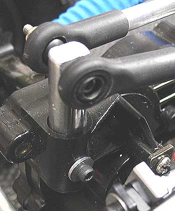
Before you can determine the axle link lengths, you will need to figure out
how and where the links will attach to the axles. There are
several options with this. We simply cut some 3/16" solid aluminum
rod and used the upper steering mount points on the axles. The rod was
filed flat on each side and drilled for rod end mounting and was drilled
again for a mounting screw to attach it to the axle. Pretty simple and highly effective.
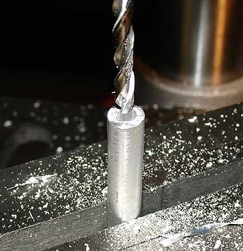
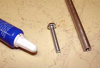
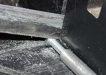
Alternatives to making your own axle mounts: 1. RC4WD.com 2. The Crawler Store How to create your own axle mounting links: 1. Purchase several lengths of 1/4" solid aluminum rod (They
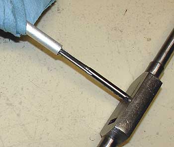
normally come in approximately 30" sections. We used two (2)
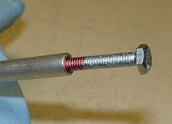
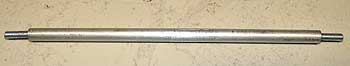
30" lengths for our project.) Go slow and use some WD-40 to lubricate the tap during the process (we know WD-40 is not a "lubricant" however it works great for tapping small holes in aluminum). It makes the tap cut easier and you will end up with nicer threads. Be sure to get the extra metal chunks out of the threads (lightly rap the links against the side of your workbench and/or use compressed air to clean them out. 7. Give each threaded hole a blast of brake cleaner to get the WD-40 out of the threads (be sure the safety glasses are on) and then let them dry or blast them out with compressed air. 8. Apply red thread locker and thread 1" long, 4-.70 bolts into the end of each rod and tighten firmly. if you tapped the holes to the correct depth, you should be able to leave about a 1/2" of the threads sticking out of the rods. 9. Cut off the bolt heads using a hack saw or Dremel. 10. Use a metal file or Dremel to smooth out the rough edges on the remaining bolt threads to make installing the rod ends easier. 11. Install the rod ends (no thread locker here!) and you are set! Note: If you were able to find a local metal working shop, they can also center drill and tap these for you. Again it is a simple procedure and should only cost you a few bucks to have it done. Also be aware that using hollow aluminum rod will enable you to avoid the drilling process listed above. You can simply tap the inside of the hollow rod and install your bolts. We considered going this route but had trouble finding the exact rod needed. Rather than waste more time trying to find the hollow stuff locally, we decided to go with the procedures listed above. Creating steering links is the same deal. Simply measure the required length keeping in mind the length of the rod ends. If you picked up a used truck are going to use the stock links as a reference, be sure they are adjusted to the desired length before using them as a template. Note that it is best to get the servo(s) mounted before fabricating the steering links. We actually made our steering links at the very end of our project, once the chassis, axle links, and all the electronics were mounted.
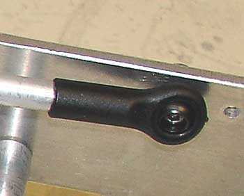
ROD ENDS
There are many rod ends on the market that will work great for a project like this. We simply took a look at the trucks in our RC stable and evaluated what they had. Out of all of our trucks, the Team Losi LST truck seemed to have the beefiest rod ends on it. So we ordered replacement rod ends for the LST and used them in our crawler project. They fit great with the 1/4" rod and give the links a lot of smooth movement.
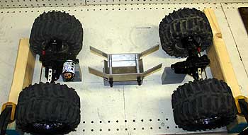
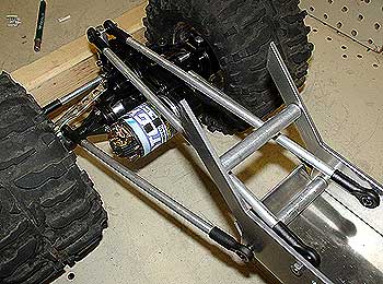
SHOCK MOUNTING
Our chassis design was made with Savage shocks in mind. We mounted stock Savage shocks to the chassis and then to the axle. Mounting the shocks to the axle versus to the lower links gave us a little more responsiveness and a more solid feel. We made some small spacers for the axle mounting points out of 3/16" aluminum rod. Shock spacers for the chassis mounting points were made from 1/4" aluminum rod.
As the shocks can run very close the the motor end caps at times, we opted to install some FullForce RC shock boots to keep those metal springs from contacting the motors. While adding some protection to our shocks and motors, they also look GREAT! Click here to check out STAGE 6 of Project Rock Ripper.....Servo Mounting. 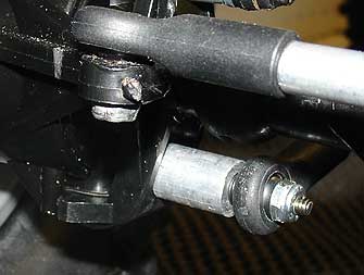 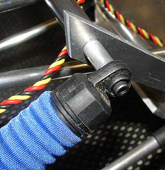 |
Advertise with Beat Your Truck * Donate to Beat Your Truck